

A replacement 12V accessory switch must match the original circuit's action, terminal functions, mounting fit, DC switching duty and illumination requirements. A similar face or matching hole is only part of the check.
Before ordering, record the original part number and obtain its diagram. Isolate all applicable power sources according to the vehicle or equipment instructions before accessing the switch; photograph terminal markings and existing connections. If the original function cannot be established, confirm it with the equipment manufacturer or a qualified installer.
| Check | Information to compare |
|---|---|
| 1. Action | Maintained or momentary; contact arrangement |
| 2. Terminals | Function, position and connector fit |
| 3. Mounting | Cutout, panel thickness and clearance |
| 4. DC duty | Voltage, load type and switching role |
| 5. Illumination | LED supply, behavior and exposure requirements |

1. Match the Action and Contact Arrangement
A maintained ON-OFF switch stays in the selected position. A momentary OFF-(ON) switch returns when released. Replacing one with the other changes how the accessory operates.
Contact arrangement matters separately: SPST switches one circuit on or off; SPDT selects between two paths. Face markings and terminal count alone cannot establish the internal connections. Compare the exact diagrams. The switch poles, throws and action guide explains these distinctions.
2. Check Terminals and Connector Fit
Record each terminal's documented function, connector form and position. Blade terminals, screw terminals and pre-wired leads require different connections. An existing plug must match the candidate's terminal layout and electrical functions, as well as its physical shape.
Illuminated models may have additional terminals for lighting. Those terminals are not automatically extra switched outputs. Wire colors and familiar-looking pin patterns are insufficient evidence of a match; use the exact model's diagram.
3. Verify the Cutout and Clearance
Compare the required panel opening, permitted panel thickness, retention method and space behind the panel. Front bezel size is not the cutout size. Allow room for terminals, connectors and wiring without forcing them against nearby parts.
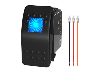
For example, DAIER DR-A11102AB and DR-A11L25A-LJ34 both list a 37 × 21 mm mounting opening. The first is a two-pin non-illuminated rocker; the second is a five-pin illuminated rocker. Matching openings do not make them wiring-compatible replacements.

4. Confirm the DC Rating and Switching Duty
Check the documented DC voltage and current rating for the intended load type. An AC-only rating does not establish DC suitability, and a “12V LED” description identifies illumination voltage rather than the contact's load capacity.
Establish whether the original switch carries accessory current or only controls a relay or electronic input. Retain the equipment's required control arrangement. The auxiliary-light component guide separates these roles.
A higher switch rating does not justify increasing the fuse. Heat damage, loose terminals or repeated fuse failure require diagnosis before replacement.
5. Match Illumination and Installation Conditions
Confirm the lamp supply voltage, any polarity requirements and the intended behavior: panel backlighting, an ON indicator or both. A replacement that lights differently may require connections that the existing harness does not provide.
Also check the documented environmental limits for the installed location, including exposed rear connections. A cover or sealed face alone does not establish protection for the complete installation.
Ordering checkpoint: proceed only when all five checks are documented. Unresolved terminal functions, ratings or mounting details need confirmation before purchase.
6. Related DAIER Products
The Rocker Switch collection provides replacement candidates. These examples serve different requirements; compatibility still depends on all five checks.

- Direct replacement candidate: DR-A11102AB two-pin rocker — maintained SPST ON-OFF, without illumination.
- Conditional illumination upgrade: DR-A11L25A-LJ34 five-pin LED rocker — maintained SPST ON-OFF; verify lighting connections separately.
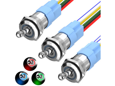
- Toggle replacement candidate: R13-401-101 toggle switch — maintained SPST ON-OFF with screw terminals.
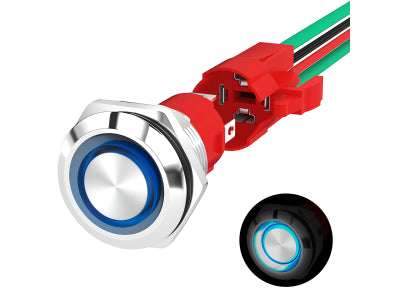
- Momentary replacement candidate: PBS-33B pre-wired push button set — OFF-(ON), for circuits requiring momentary operation.


