Eliminating Parasitic Drain and Mastering Professional Circuit Integration
It is a frustration known to many in the 4x4, marine, and RV communities: a weekend spent perfecting a dashboard layout, only to find a persistent "phantom glow" emanating from the rocker switches long after the engine has been cut. While a single glowing LED might seem like a minor aesthetic quirk, in the world of 12V electrical engineering, it represents a fundamental flaw in wiring logic known as Parasitic Drain.
Leaving an LED backlight on 24/7 is not a manufacturing defect; it is a choice made during the termination of the wires. This guide will dissect the internal architecture of the 5-pin rocker switch, calculate the real-world impact on battery longevity, and provide three distinct professional wiring schematics to ensure the system is as reliable as it is functional.

Internal Architecture: Understanding the 5-Pin Schematic
To fix a circuit, one must first understand its internal mechanical behavior. A standard 5-pin rocker switch (specifically the high-quality variants produced by Daier) is essentially two circuits housed in one body: a Load Circuit and a Lighting Circuit.
The Terminal Map (Standard Configuration):
-
Pin 8 & 7 (The Grounds): These are the negative terminals for the internal LEDs. Pin 8 is typically the ground for the lower LED (the symbol), and Pin 7 is the ground for the upper LED (the status light).
-
Pin 2 (Power In/Line): This is the main input that will be switched to the load.
-
Pin 3 (Power Out/Load): This terminal becomes energized only when the switch is moved to the "ON" position, sending power to your relay or accessory.
-
Pin 6 (Upper LED Positive): This controls the independent illumination of the bottom icon. This is almost always the source of the "Always On" issue.

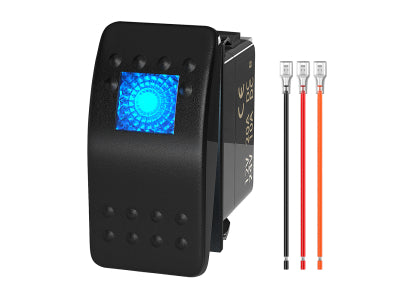
Figure 1: Physical Pinout Identification. Understanding the location and function of each terminal is the first step toward a professional installation.
The Math of Failure: Calculating Parasitic Drain
Why is a "tiny LED" a problem? Let's look at the raw data. A high-efficiency LED in a rocker switch draws approximately 20mA to 30mA (0.02A - 0.03A).
If a dashboard features a 6-switch panel with the "Always On" wiring logic, the total draw is 180mA (0.18A). Over 24 hours, this consumes 4.32 Amp-hours (Ah). After five days of the vehicle sitting idle, you have lost over 21Ah of capacity.
For an average 80Ah lead-acid battery, this draw, combined with the vehicle's own parasitic computer systems, can drop the voltage below the starting threshold (approx. 11.8V), especially in cold weather. Professional builds prioritize Zero-Key-Off-Draw.

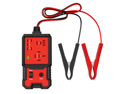
Figure 2: A real-world test showing a 0.2A parasitic draw (left). Over time, this constant drain pushes your battery into the "Danger Zone" (right), where voltage drops below the starting threshold.
Three Solutions for Professional Wiring Logic
To stop the LED from staying on, Pin 6 must be disconnected from the "Always On" battery source. Here are the three most practical methods:
1. The "ACC" Trigger (Ignition-Switched Power)
This is the most common fix. Connect Pin 6 to a circuit that is only live when the key is in the "ACC" or "ON" position.
-
How-to: Use an Add-a-Circuit Fuse Tap to pull power from a non-essential fuse (like the radio or cigarette lighter) in the cabin fuse box.
-
Result: The switch backlights turn on when you start the vehicle and cut off completely when you remove the key.
2. The "OEM" Integration (Dashboard Dimmer Circuit)
For a factory-perfect look, connect Pin 6 to the vehicle's illumination circuit.
-
How-to: Locate the wire that powers your factory dashboard buttons (usually found behind the dimmer switch or climate control). Use a T-Tap Connector to link Pin 6 to this wire.
-
Result: The switches only glow when you turn on your headlights, matching the brightness and behavior of your factory dashboard.
3. The "Independent Ground" Loop (Advanced Diagnosis)
Sometimes the LED stays on because of Residual Voltage back-feeding through the ground.
-
The Problem: If Pin 7 and 8 are shared with a ground that has high resistance, current can actually "leak" back through the LED.
-
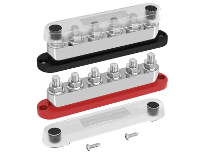
The Fix: Ensure Pin 7 and 8 have a dedicated, clean path to a Ground Bus Bar. Never daisy-chain grounds for more than 3 switches in a high-draw system.

Figure 3.1: Wiring Method 1 — Upper LED Always ON
In this configuration, Pin 6 is jumped directly to the constant power input (Pin 2). The upper status light remains illuminated 24/7, even when the ignition is off. While this makes the switch easy to locate in total darkness, it creates a constant parasitic draw on the battery.

Figure 3.2: Wiring Method 2 — All Lights OFF When Switched Off
This is the "Zero-Draw" professional configuration. By connecting the illumination circuit (Pin 6) to the load output (Pin 3), both LEDs remain completely dark when the switch is in the OFF position. This is the safest method to ensure zero battery depletion during long periods of storage.

Figure 3.3: Wiring Method 3 — Lower Icon Always ON
This configuration powers the lower functional icon independently. By supplying constant power to the lower LED and tying the upper LED to the switch status, you can identify the switch function at night without the distraction of the larger upper status bar glowing constantly.
Troubleshooting "Ghost Glow" and Dim LEDs
In some cases, the LED might still glow faintly even after disconnecting the main power. This is not magic; it is physics.
1. Inductive Coupling: If your signal wires are bundled tightly for long distances alongside high-current AC or pulsing DC wires, they can pick up a tiny "ghost voltage" via induction.
- Fix: Use shielded wire or separate your signal wires from high-draw power cables.
2. Back-Feeding from the Relay: A low-quality relay can allow a small amount of current to leak back from the coil through the trigger wire (Pin 3 or 6).
- Fix: Use a Relay with a Built-in Diode. The diode acts as a one-way valve, ensuring current only flows to the relay and never back from it.
Engineering Best Practices for Rocker Switches
To avoid troubleshooting in the future, adhere to these professional standards during installation:
-
Terminal Selection: Use Heat-Shrink Female Spades. Standard nylon terminals eventually vibrate loose and admit moisture, leading to the corrosion and resistance issues we discussed.
-
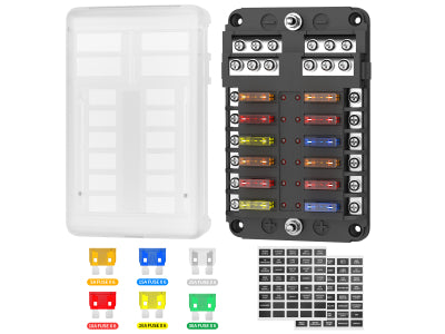
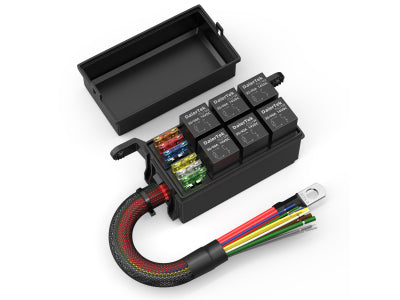
Circuit Protection: Every switch panel should have its own dedicated fuse. A 6-Way or 12-Way Fuse Block is the best way to keep your dash organized and safe.
-
Labeling: Never rely on memory. Use a label maker to mark the function of every wire behind the dash. A year from now, you (or the next owner) will be grateful.
Conclusion: Built for Longevity
An "Always On" rocker switch is a signal that a project is incomplete. By moving the illumination trigger (Pin 6) to an ACC or Dashboard light source, you transform a potential battery drain into a professional-grade control system. Reliability in the field is not about having the flashiest gear; it is about ensuring that every electron in your circuit is doing exactly what you intended.
Ready to upgrade your dashboard? Explore our Professional Grade Rocker Switches and Pre-Wired Relay Boxes to build a system that stands the test of time.


