



A Step-by-Step Engineering Approach to Identifying Resistance, Voltage Drop, and Component Failure
In 12V electrical systems, failure is rarely a mystery; it is physics. Whether it is a dead winch on a Jeep or a non-responsive bilge pump on a boat, the diagnostic process remains identical. A circuit is a continuous loop. If the loop is broken, or if resistance becomes too high, the system fails.
This guide moves away from the "parts-swapping" mentality and introduces a professional diagnostic pathway. By using a Digital Multimeter (DMM) and a logical process of elimination, any failure can be isolated and corrected.

The First Principle: Verifying the Heart (State of Charge)
Before inspecting wires or switches, the potential energy at the source must be verified. A 12V battery is not simply "on" or "off." Its state of charge dictates the behavior of the entire system.
-
Resting Voltage: A fully charged Lead-Acid or AGM battery should read 12.6V to 12.8V. If the meter reads 12.2V, the battery is at 50% capacity. If it reads below 10.5V, a cell is likely damaged.
-
The Load Test: A battery can show 12.6V but collapse to 6V the moment a high-amp load (like a winch) is applied. Measure the voltage at the battery terminals while attempting to activate the failed device. A drop below 10V during load indicates a weak or failing battery.
To understand the relationship between potential and flow, review the 12V DC Fundamentals Guide.
The Gateway: Primary and Secondary Protection
If the source is stable, the next point of failure is often the protection device—the fuse or circuit breaker.
-
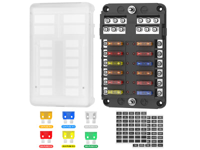
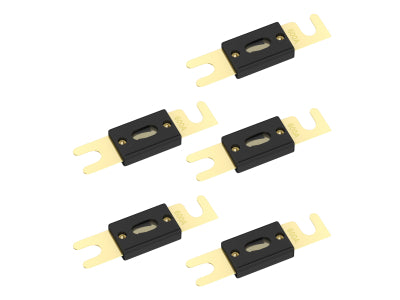
Continuity Testing: Do not rely on a visual inspection of a fuse. A hairline fracture in the metal bridge can be invisible. Set the multimeter to the Continuity (Beep) setting. Touch the test points on top of the fuse. No beep means the fuse is blown.
-
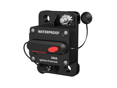
The Breaker Trip: If using a Manual Reset Circuit Breaker, verify the reset lever is seated. If a breaker trips immediately after being reset, a Dead Short exists. This means a positive wire is making direct contact with the chassis or a negative lead.

The Command Center: Switches and Relays
Mechanical components are prone to wear, especially in high-vibration off-road or marine environments.
-
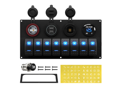
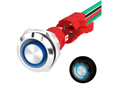
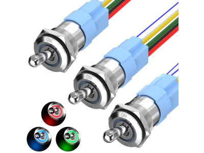
Switch Bypass Test: To isolate a faulty switch, bridge the "Power In" and "Power Out" terminals with a fused jumper wire. If the device activates, the switch internal contacts are oxidized or burnt.
-
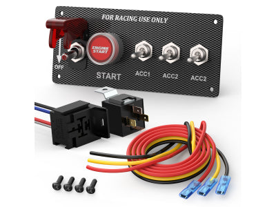
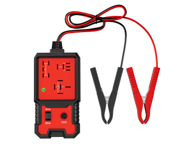
The Relay Logic: If the circuit uses a Relay, there are two distinct sides to test.
-
-
The Trigger (85 & 86): When the switch is on, is there 12V across the relay coil?
-
The Load (30 & 87): If the relay clicks but no power reaches the device, the internal high-current contacts have failed.
-
If the wiring looks like a "spaghetti mess," consult our Relay Wiring Blueprint to re-organize the circuit correctly.
The Hidden Culprit: Voltage Drop and Resistance
This is the most critical part of professional troubleshooting. A circuit can have "voltage" but not enough "current" to do work. This is caused by Voltage Drop.
Understanding Resistance: Corroded terminals, loose crimps, or undersized wires act like a kink in a hose. They restrict flow and generate heat.
The Voltage Drop Test: This is performed while the circuit is ON and under load.
Place the red probe on the Battery Positive (+).
Place the black probe on the Positive terminal of the device (e.g., the light bar).
A reading over 0.5V indicates excessive resistance in the positive wire. Repeat this for the Negative side.

The Ground Path: The Most Common Failure
In 4x4 and marine applications, the ground is just as important as the power. Most builders overlook the negative side of the loop.
- Chassis Ground vs. Dedicated Ground: On a vehicle, the metal body is the ground. If a bolt is rusty or painted, the circuit is broken. On a boat, a dedicated ground bus bar is used.
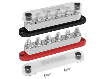
- The "Ghost Ground": A bad ground can cause devices to behave strangely—lights dimming when a pump turns on, or back-feeding through other circuits. Ensure all Bus Bars and negative terminals are clean, tight, and protected with dielectric grease.
Bench Testing the Load (The Final Step)
If you have verified 12.6V at the device, a perfect ground, and zero voltage drop, but the device still won't work, the "Load" itself is dead.
- The Direct Jump: Use a pair of fused jumper wires to connect the device directly to a known-good battery. If the light bar doesn't illuminate or the pump doesn't spin, the internal motor or circuitry has failed.
Conclusion: Logic Over Luck
Successful 12V troubleshooting is about isolating segments of the circuit until the failure is found. Never assume a new part is good, and never underestimate the power of a bad ground. By measuring voltage under load and checking for continuity, you move from "guessing" to "knowing."
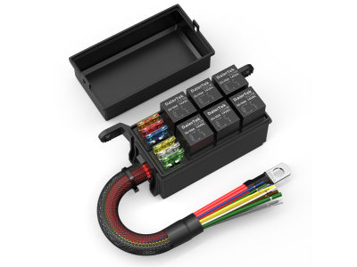
Still encountering issues? Explore our professional range of Heavy-Duty Switches, Fuses, and Distribution Blocks to ensure your next build is engineered for reliability.


