
Anleitung zum Anschließen eines 5-poligen LED-Wippschalters: Eine bebilderte Anleitung
Meistern Sie den gängigsten beleuchteten Ein-/Ausschalter für einen professionellen Look
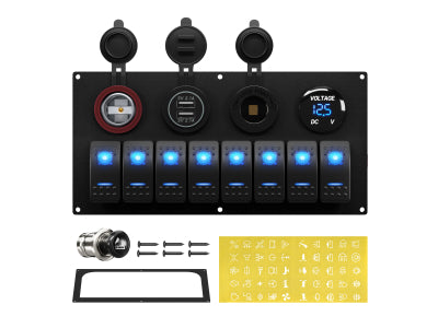
Sie kennen sie von den elegantesten, individuell gestalteten LKW-Armaturenbrettern und den professionellsten Bedienfeldern von Booten: Kippschalter mit sanfter Hintergrundbeleuchtung, die beim Einschalten ein zweites, helleres Symbol aufleuchten lassen. Dies ist der 5-polige SPST-Kippschalter (Single Pole, Single Throw) zum Ein- und Ausschalten – der Goldstandard für eine professionell wirkende Installation.
Doch mit fünf Pins auf der Rückseite kann die Verdrahtung im Vergleich zu einem einfachen 2-Pin-Schalter kompliziert erscheinen. Wozu dienen all diese Anschlüsse?
Keine Sorge. Das Geheimnis ist ganz einfach: Sie verdrahten zwei separate, leicht verständliche Schaltkreise in einem Bauteil. Diese Anleitung erklärt Ihnen alles Schritt für Schritt anhand übersichtlicher Diagramme und unserer Video-Anleitung, damit auch Sie im Handumdrehen zum Experten werden.

Warum einen beleuchteten 5-poligen Wippschalter verwenden?
Bevor wir mit dem Verdrahten beginnen, wollen wir die Vorteile verstehen, die diesen Schalter so beliebt machen:
-
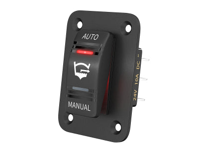
Unabhängige Hintergrundbeleuchtung: Die untere Hälfte des Schalters (oft die Beschriftung) kann an den Beleuchtungskreis des Armaturenbretts Ihres Fahrzeugs angeschlossen werden. Wenn Sie das Abblendlicht einschalten, leuchten alle Schalter sanft und gleichmäßig, sodass sie auch im Dunkeln gut zu finden sind.
-
"EIN"-Anzeige: Die obere Hälfte des Schalters (das Symbol) leuchtet nur auf, wenn der Schalter eingeschaltet ist. Dadurch erhalten Sie sofort eine visuelle Bestätigung, dass Ihr Zubehör – wie beispielsweise eine Lichtleiste oder eine Pumpe – aktiv ist.
-
Professionelle Ästhetik: Es sieht einfach sauber, harmonisch und professionell aus.
Die 5 Pins verstehen: Zwei Schaltkreise in einem Schalter
Der Schlüssel zum Anschließen dieses Schalters liegt darin, ihn nicht als ein Bauteil mit fünf verwirrenden Pins zu betrachten. Stellen Sie ihn sich stattdessen so vor: zwei unabhängige Stromkreise In einem gemeinsamen Gehäuse befinden sich ein Hauptschalterkreis und ein Beleuchtungskreis.
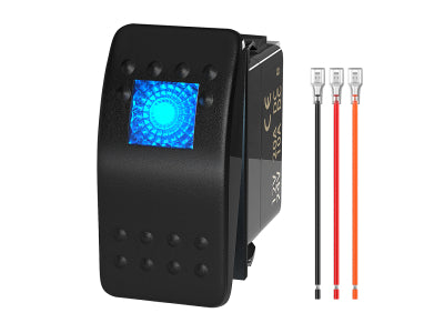
Schauen wir uns die Rückseite eines typischen Schalters an. Die Pins sind deutlich nummeriert.

Der Hauptschalterkreis (Pins 2 & 3)
Dies ist der einfache EIN-AUS-Teil.
-
Pin 2 (Stromeingang): Dies ist der Stromeingang für den Schalter. Er wird mit 12 V von Ihrer abgesicherten Stromquelle versorgt.
-
Pin 3 (Stromausgang): Wenn Sie den Schalter einschalten, wird intern eine Verbindung zu Pin 2 hergestellt. Dieser Pin sendet die 12-V-Spannung. aus an Ihr Zubehör (oder genauer gesagt, an den Auslöser Ihres Relais - Pin 86).
Der Beleuchtungskreis (Pins 7, 6 und 8)
Dies ist der Teil, der die beiden eingebauten LEDs steuert.
-
Pin 7 (Negativ IN): Dies ist die Hauptplatz Dies gilt für beide internen LEDs. Es muss an eine gute Masseverbindung am Chassis oder an die negative Sammelschiene angeschlossen werden.
-
Pin 6 (Pluspol IN für untere "Armaturenbrett"-Leuchte): Dieser Pin versorgt die untere, dezente Hintergrundbeleuchtung mit Strom. Um sie zusammen mit der übrigen Armaturenbrettbeleuchtung einzuschalten, schließen Sie ihn an den vorhandenen Stromkreis der Armaturenbrettbeleuchtung Ihres Fahrzeugs an (oft durch Anzapfen des Beleuchtungskabels eines nahegelegenen Schalters).
-
Pin 8 (Minuspol OUT für obere "EIN"-Leuchte): Dieser Pin ist für die obere Kontrollleuchte. Und hier kommt der Clou: Die obere Leuchte erhält ihre positive Spannung intern von Pin 2, wenn der Schalter eingeschaltet ist. Pin 8 hat folgende Aufgabe: einen Weg zum Boden schaffen Dadurch wird der Stromkreis für diese Lampe geschlossen und sie eingeschaltet. Da sie über Pin 7 mit der Hauptmasse verbunden ist, geschieht dies automatisch.
So verdrahten Sie Ihren 5-poligen Wippschalter (Schritt für Schritt)
Für visuelle Lerntypen bietet unsere vollständige Videoanleitung eine detaillierte Beschreibung des gesamten Prozesses.
Eine schriftliche Anleitung finden Sie in den folgenden Schritten unter Berücksichtigung der unten stehenden Diagramme.
-
Sicherheit geht vor: Trennen Sie den Minuspol der Fahrzeugbatterie.
-
Hauptstromanschluss (Pin 2): Verlegen Sie ein Kabel von einer abgesicherten 12V-Quelle zu Pin 2. Hierüber wird Ihr Zubehör mit Strom versorgt.
-
Anschluss an Zubehör/Relais (Pin 3): Verlege ein Kabel von Pin 3 zum Auslöser Ihres Relais (Pin 86 eines Standardrelais). Zur Erinnerung: Dieser Schalter ist für 20 A ausgelegt, aber für Geräte mit hohem Stromverbrauch wie Lichtleisten, Pumpen oder Seilwinden sollten Sie IMMER ein Relais verwenden.
-
Schließen Sie die Hauptmasse (Pin 7) an: Verlege ein Kabel von Pin 7 an eine solide Masseverbindung am Chassis oder an die Masseschiene anschließen. Dies ist entscheidend für die Funktion beider Leuchten.
-
Schließen Sie die Stromversorgung der Armaturenbrettbeleuchtung an (Pin 6): Suchen Sie an einem nahegelegenen Werksschalter ein Kabel, das nur dann 12 V führt, wenn Ihre Scheinwerfer/Armaturenbrettbeleuchtung eingeschaltet ist. Zapfen Sie dieses Kabel an und führen Sie es zu Pin 6. Dadurch wird die Hintergrundbeleuchtung Ihres neuen Schalters gedimmt und schaltet sich zusammen mit den anderen ein.
-
Pin 8 benötigt keine externe Verbindung. Es ist intern mit der von Ihnen an Pin 7 angegebenen Masse verbunden.
-
Finalisieren und testen: Schließen Sie die Batterie wieder an. Die untere Kontrollleuchte am Schalter sollte zusammen mit der Armaturenbrettbeleuchtung aufleuchten. Beim Betätigen des Schalters sollte die obere Kontrollleuchte hell aufleuchten und Sie sollten ein Klicken des Relais hören.
Erweiterte Verdrahtungsoptionen: Individuelle Anpassung der Schalterbeleuchtung
Nachdem Sie die Standardinstallation für Fachleute beherrschen, wollen wir uns nun mit anderen gängigen Methoden befassen. Der Vorteil des 5-poligen Schalters liegt in seiner Vielseitigkeit. Je nach Bedarf können Sie die Verkabelung leicht anpassen, um das Verhalten der Kontrollleuchten zu verändern.
Methode A: Die professionelle „Armaturenbrettbeleuchtung“-Konfiguration (Empfohlen)
Dies ist die oben beschriebene Methode. Sie bietet eine unabhängige Hintergrundbeleuchtung, die mit den Armaturenbrettleuchten Ihres Fahrzeugs synchronisiert wird, und eine separate „EIN“-Anzeige.
-
So funktioniert es: Die untere „Wort“-Leuchte wird vom Armaturenbrettlichtkreis versorgt. Die obere „Symbol“-Leuchte leuchtet nur, wenn der Schalter eingeschaltet ist.
-
Ideal für: Ziel ist ein sauberer, werkseitiger/OEM-Look, bei dem alle Schalter auch im Dunkeln bei eingeschaltetem Abblendlicht leicht zu finden sind.
-
Diagramm

Methode B: Die einfache "aktive Indikator"-Konfiguration
Dies ist die einfachste Art, den Schalter anzuschließen, wenn die Lichter nur dann angehen sollen, wenn das Zubehör aktiv ist.
-
So funktioniert es: Sowohl die obere als auch die untere LED werden nur dann mit Strom versorgt, wenn der Schalter eingeschaltet ist. Im ausgeschalteten Zustand ist es völlig dunkel. Dies wird durch das Überbrücken der beiden Pluspole erreicht.
-
Ideal für: Für Anfänger, minimalistische Setups oder Situationen, in denen Sie kein zusätzliches Licht auf Ihrem Armaturenbrett wünschen, es sei denn, das Gerät ist in Betrieb.
-
Diagramm

Dazu verbinden Sie einfach den Hauptstromanschluss (von Pin 2) mit dem Stromanschluss für die Hintergrundbeleuchtung (Pin 6) mithilfe eines kleinen Jumperkabels.
Methode C: Die Einrichtung der „Locator Light“ (immer eingeschaltete Hintergrundbeleuchtung)
Was aber, wenn Sie den Schalter auch im Dunkeln finden möchten, selbst wenn Ihre Armaturenbrettbeleuchtung ausgeschaltet ist? Diese Methode hält die untere Hintergrundbeleuchtung dauerhaft eingeschaltet.
-
So funktioniert es: Die untere „Wort“-Leuchte ist an eine konstante 12V-Stromquelle angeschlossen (immer an), während die obere „Symbol“-Leuchte weiterhin nur dann aufleuchtet, wenn der Schalter aktiv ist.
-
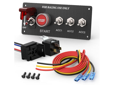
Ideal für: Kritische Ausrüstung in Rennwagen, Booten oder Nutzfahrzeugen, bei der man jederzeit, Tag und Nacht, sofort einen Schalter finden muss.
-
Diagramm

Notiz: Diese Methode erzeugt einen sehr geringen, aber konstanten Stromverbrauch Ihrer Batterie.
Fazit: Erzielen Sie einen professionellen Look mit Selbstvertrauen
Das war's! Durch die Aufteilung in einen einfachen Schalterkreis und einen Beleuchtungskreis wird der 5-polige Wippschalter leicht verständlich. Es ist ein einfaches Upgrade, das die Funktion und das Aussehen jedes Bedienfelds deutlich verbessert.
Bereit, Ihr eigenes individuelles Schalterpanel zu bauen? Entdecken Sie hier unser gesamtes Sortiment an 5-Pin-Wippschaltern und Zubehör.
Hinterlassen Sie einen Kommentar