Lernen Sie den beleuchteten Wippschalter mit Starlink-Symbol kennen: Intelligente Stromsteuerung für Ihr mobiles und netzunabhängiges Setup
 Einleitung: Frustriert von der generischen Starlink-Stromsteuerung? Es gibt eine bessere Lösung.
Sie haben sich also für Starlink entschieden, um in Ihrem Wohnmobil, Boot oder Ihrer netzunabhängigen Unterkunft einen unglaublichen Internetzugang zu erhalten. Das ist bahnbrechend! Aber seien wir ehrlich: Die Verwaltung der Stromversorgung in einer benutzerdefinierten Konfiguration kann sich manchmal wie eine Nebensache anfühlen. Sind Sie es leid:
-
Suchen Sie auf einem überfüllten Bedienfeld nach einem nicht gekennzeichneten, generischen Schalter?
-
Sie fragen sich, ob Ihr Starlink Genau genommen ausgeschaltet und möglicherweise wertvolle Batterie entladen?
-
Ihnen fehlt eine saubere, professionell aussehende Steuerung, die zu Ihrem Hightech-Starlink-System passt?
-
Müssen Sie zu einer zentralen Stromschalttafel gehen, um den Strom abzuschalten, anstatt bequem darauf zugreifen zu können?
Wenn Ihnen das bekannt vorkommt, sind Sie nicht allein. Viele Starlink-Benutzer suchen nach einer eleganteren und praktischeren Lösung.
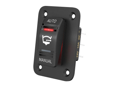
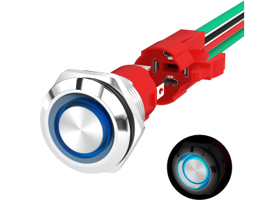
Lernen Sie den beleuchteten Wippschalter mit Starlink-Symbol kennen . Er basiert auf einem zuverlässigen 5-poligen Ein-/Aus-Wippschalter , sein wahrer Wert liegt jedoch im Starlink-spezifischen Design, der doppelten Beleuchtung mit Starlink-Logo und WLAN-Symbol sowie der robusten Konstruktion. Dieser Schalter löst die üblichen Probleme bei der Leistungssteuerung und lässt sich nahtlos in Ihr 12-V- oder 24-V-DC-Starlink-Setup integrieren.

Warum dieser spezielle 5-Pin-Schalter ein Starlink-Game-Changer ist
Dies ist nicht irgendein 5-poliger Kippschalter. Er wurde von Grund auf entwickelt, um die Bedürfnisse von Starlink-Benutzern zu erfüllen:
-
Das Problem: Generischen Schaltern fehlt es an Identität und Klarheit.
-
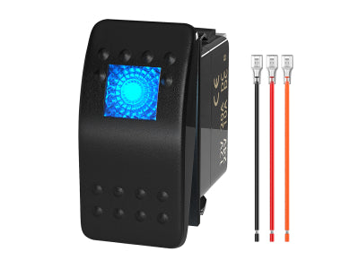
Die Lösung: Gezieltes Starlink-Branding. Mit dem unverwechselbaren Starlink-„X“-Logo und einem WLAN-Symbol zeigt Ihnen dieser Schalter sofort seine Funktion an. Schluss mit Rätselraten auf Ihrem Bedienfeld. Er verleiht Ihrer Starlink-Wohnmobilinstallation oder Ihrem Starlink-Boots-Setup einen Hauch von professionellem, durchdachtem Design .
-
-
Der Schmerz: Unsicherheit über den Stromstatus, insbesondere im Dunkeln.
-
Die Lösung: Klare Dual-LED-Beleuchtung. Die integrierten LEDs geben sofortiges visuelles Feedback. Und dank des vielseitigen 5-Pin-Designs (normalerweise werden die Pins 1, 2, 3, 6 und 7 als aktiv verwendet – siehe Abschnitt „Verdrahtung“) können Sie die Funktionsweise wählen:
-
Ortungsgerät + Aktivanzeige: Eine LED leuchtet immer (wenn das Panel mit Strom versorgt wird), damit Sie den Schalter leicht finden können, die andere leuchtet, wenn Starlink aktiv ist.
-
Nur aktive Anzeige: Beide LEDs leuchten nur, wenn Starlink eingeschaltet ist.


-
-
-
Das Problem: Schalter versagen unter schwierigen mobilen oder Außenbedingungen.
-
Die Lösung: Gebaut für Abenteuer mit IP66-Schutz. Dieser wasserdichte Starlink-Schalter ist vollständig staubdicht und gegen starkes Strahlwasser geschützt. Ob Regen, Spritzwasser oder Staub – er ist so konzipiert, dass er in Ihrer Starlink-Marineanwendung oder Ihrem robusten Überlandfahrzeug zuverlässig funktioniert.

-
-
Das Problem: Die Sorge, ob ein Switch den Stromverbrauch von Starlink bewältigen kann.
-
Die Lösung: Robuste Nennleistung. Mit einer Nennleistung von 20 A bei 12 V DC und 10 A bei 24 V DC ist dieser Schalter bei Integration in einen ordnungsgemäß abgesicherten Gleichstromkreis mehr als in der Lage, die Stromversorgung verschiedener Starlink-Systeme, von Standard bis Hochleistung, zu bewältigen.
-
-
Das Problem: Komplexe oder unordentliche benutzerdefinierte Verkabelung.
-
Die Lösung: Standardisiertes 5-Pin-Design und mitgelieferte Überbrückungskabel. Passt in einen gängigen Wippschalterausschnitt. Der Schalter nutzt 5 aktive Pins für Stromversorgung und LED-Steuerung (Pins 1, 2, 3, 6, 7 wie in typischen Diagrammen für dieses Produkt dargestellt – andere Markierungen wie 4, 5, 8 auf dem Gehäuse sind bei solchen 5-Pin-Varianten oft intern nicht verbunden). Die mitgelieferten vorkonfektionierten Überbrückungskabel vereinfachen das Erreichen des gewünschten LED-Verhaltens.

-
Lösung realer Starlink-Stromversorgungsprobleme: Szenarien und Vorteile
Stellen Sie sich diese häufigen Situationen vor und wie dieser spezielle Starlink-Netzschalter das Leben einfacher macht:
-
Der RV-Benutzer:
-
Schmerzpunkt: Ständige Sorge wegen der Batterieentladung durch Starlink beim Wildcampen oder wegen des Zugriffs auf einen vergrabenen Hauptschalter.
-
Lösung: Mit dem am Armaturenbrett montierten Starlink-Schalter können Sie die Stromversorgung vor der Abfahrt, beim Verlassen des Wohnmobils oder wenn Sie einfach kein Internet benötigen, sofort unterbrechen und so die Batterielebensdauer maximieren. Dank des beleuchteten Symbols finden Sie den Schalter auch nachts leicht.
-
-
Der Bootsfahrer/Marinenutzer:
-
Schmerzpunkt: Beim Andocken, Ankern oder zum Energiesparen auf längeren Reisen müssen elektronische Geräte, einschließlich Starlink, schnell heruntergefahren werden. Salznebel und Feuchtigkeit stellen für elektronische Geräte eine ständige Bedrohung dar.
-
Lösung: Ein IP66-zertifizierter Schalter am Steuerstand sorgt für komfortable und zuverlässige Steuerung. Schalten Sie Starlink mit einem Handgriff aus, denn der Schalter ist für die Meeresumgebung geeignet. Perfekt für Ihr selbstgebautes Starlink-Bootsstromversorgungssystem .
-
-
Der netzunabhängige Selbstversorger:
-
Schmerzpunkt: Jedes Watt zählt. Wenn Starlink unnötig eingeschaltet bleibt, können sorgfältig verwaltete Solar- oder Batteriereserven erschöpft werden.
-
Lösung: Ein deutlich gekennzeichneter, leicht zugänglicher Schalter stellt sicher, dass Starlink nur dann mit Strom versorgt wird, wenn es aktiv benötigt wird, und unterstützt so das wichtige netzunabhängige Energiemanagement von Starlink .
-
-
Jeder mit einem benutzerdefinierten Setup:
-
Schmerzpunkt: Sie möchten lieber ein sauberes, professionelles Erscheinungsbild als eine unpassende Sammlung generischer Teile. Sie haben Schwierigkeiten, sich zu merken, welcher Schalter was bewirkt.
-
Lösung: Das Starlink-Branding sorgt für sofortige Wiedererkennung und eine elegante Ästhetik. Es ist der letzte Schliff für ein gut durchdachtes Starlink-Bedienfeld .
-
Im Wesentlichen bietet dieser Switch:
-
Bequemlichkeit: Kein Greifen, Herumtasten oder Hinterfragen mehr.
-
Energieeinsparungen: Verhindern Sie ganz einfach unnötigen Batterieverbrauch.
-
Seelenfrieden: Sie können sicher sein, dass Ihr Starlink ausgeschaltet ist, wenn Sie es möchten.
-
Haltbarkeit: Zuverlässiger Betrieb in verschiedenen Umgebungen.
-
Verbesserte Ästhetik: Ein professionelles Aussehen für Ihre wertvolle Starlink-Investition.
Verkabelung Ihres 5-poligen Starlink-Schalters: Eine klare Anleitung
Dieser Schalter verwendet eine gängige 5-Pin-Konfiguration für die Stromversorgung und die Dual-LED-Steuerung. Basierend auf den typischen Diagrammen, die mit diesem Produkt geliefert werden, sind die aktiven Pins normalerweise:
-
Stift 2: Power IN (+) (von Ihrer abgesicherten 12V/24V-Quelle)
-
Stift 3: Power OUT (+) (zu Ihrem Starlink-System oder seinem DC-DC-Konverter/Wechselrichter)
-
Stift 7: Gemeinsame Masse (-) (für LEDs und kann dort sein, wo der Minuspol des Starlink-Systems angeschlossen wird)
-
Stift 1: Obere LED positiv (+)
-
Stift 6: Untere LED positiv (+)
(Hinweis: Die mit 4, 5 und 8 gekennzeichneten Pins am Schaltergehäuse sind bei dieser 5-poligen Variante in der Regel nicht intern verbunden. Beachten Sie immer das spezifische Diagramm, das mit IHREM Schalter geliefert wurde!)
So funktionieren die beiden gängigen Verbindungsmethoden mit diesen 5 Pins:
Anschlussmethode 1: Eine LED leuchtet immer (Locator), andere LED leuchtet bei Last
-
Batterie Plus (+) Zu Stift 2 (Hauptstromversorgung) UND Jumper zu Stift 1 (Obere LED immer an).
-
Batterie Minus (-) Zu Stift 7 (Gemeinsame Masse für LEDs und Last).
-
Stift 3 (Ausladen) zu Starlink Positiv (+) .
-
Pullover von Stift 3 (Ausladen) zu Stift 6 (Untere LED leuchtet, wenn Starlink eingeschaltet ist).
-
Starlink Negativ (-) Zu Batterie Minus (-) (kann am selben Punkt wie Pin 7 angeschlossen werden).
Ergebnis: Das Starlink-Logo (obere LED) leuchtet immer, wenn das Hauptpanel mit Strom versorgt wird, sodass der Schalter leicht zu finden ist. Das WLAN-Symbol (untere LED) leuchtet nur, wenn Sie den Schalter einschalten, um Starlink mit Strom zu versorgen.

Verbindungsmethode 2: Beide LEDs leuchten, wenn Starlink mit Strom versorgt wird
-
Batterie Plus (+) Zu Stift 2 (Hauptstromeingang).
-
Pullover von Stift 2 (Hauptstromeingang) auf Stift 1 (Obere LED positiv). Korrektur: Damit beide LEDs unter Last leuchten, muss Pin 1 zusätzlich von Pin 3 gesprungen werden, ansonsten vereinfacht sich das Diagramm. Wir folgen dem bereitgestellten Diagramm genauer, falls es einen einfacheren internen Sprung für die obere LED in diesem Modus impliziert.
Schauen wir uns das Diagramm für Methode 2 noch einmal an:-
Batterie (+) an Pin 2.
-
Pin 1 ist mit Pin 2 verbunden (die obere LED wird also mit Strom versorgt, wenn der Schalter könnte eingeschaltet sein, benötigt aber Erdung).
-
Pin 7 zur Batterie (-) (Masse für obere LED).
-
Pin 3 an Last (+).
-
Pin 6 hat einen Sprung von Pin 3 (die untere LED wird mit Strom versorgt, wenn die Last eingeschaltet ist).
-
Dies bedeutet, dass die obere LED (Starlink-Logo) aufleuchtet, wenn der Schalter eingeschaltet ist, weil Pin 2 unter Spannung steht und Pin 7 Masse ist und der interne Schaltmechanismus Pin 2 mit Pin 3 verbindet. Die untere LED (WLAN) leuchtet auf, weil Pin 3 unter Spannung steht. Das funktioniert.
-
-
Batterie Minus (-) Zu Stift 7 (Gemeinsame Masse für LEDs und Last).
-
Stift 3 (Ausladen) zu Starlink Positiv (+) .
-
Pullover von Stift 3 (Ausladen) zu Stift 6 (Untere LED positiv).
-
Starlink Negativ (-) Zu Batterie Minuspol (-) .
Ergebnis: Sowohl das Starlink-Logo als auch das WLAN-Symbol leuchten nur auf, wenn sich der Schalter in der Position „ON“ befindet, was eine starke visuelle Bestätigung darstellt.
Sicherheit geht vor! Trennen Sie vor der Verkabelung immer die gesamte Stromversorgung. Wenden Sie sich im Zweifelsfall an einen qualifizierten Techniker. Stellen Sie sicher, dass Ihr Stromkreis für die Stromaufnahme Ihres Starlink-Systems ausreichend abgesichert ist.

Warum dieser dedizierte 5-polige Starlink-Schalter Ihre beste Wahl ist
Sie könnten jeden 5-poligen Wippschalter verwenden, aber warum sollten Sie sich mit einem generischen zufrieden geben, wenn Sie eine Lösung haben können, die:
-
Zweck-Symbol: Identifiziert eindeutig seine Funktion für Ihr Starlink.
-
Optimiert für Sichtbarkeit: Doppelte LEDs nach Wunsch konfiguriert.
-
Für die Ewigkeit gebaut: Schutzart IP66 für anspruchsvolle Umgebungen.
-
Einfach zu integrieren: Standardgröße und klare 5-polige Verkabelung.
Es handelt sich um ein intelligentes, einfaches Upgrade, das einen großen Unterschied in der Art und Weise macht, wie Sie täglich mit Ihrem Starlink-System interagieren und es verwalten.
Fazit: Übernehmen Sie einfach und stilvoll die Kontrolle über Ihre Starlink-Leistung
Lassen Sie die Starlink-Energieverwaltung nicht länger als kleines Ärgernis erscheinen. Der beleuchtete 5-polige Wippschalter mit Starlink-Symbol bietet eine raffinierte, zuverlässige und praktische Lösung, die speziell auf Starlink-Benutzer zugeschnitten ist. Er behebt häufige Schwachstellen mit seinem durchdachten Design, der robusten Bauweise und der klaren visuellen Rückmeldung.
Rüsten Sie noch heute Ihr Wohnmobil, Boot oder Ihre netzunabhängige Anlage auf und erleben Sie den Unterschied, den ein dedizierter Starlink-Switch ausmachen kann.
Bereit für die problemlose Starlink-Stromsteuerung? Wippschalter mit Starlink-Symbol.
Hinterlassen Sie einen Kommentar