

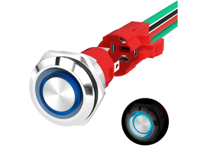
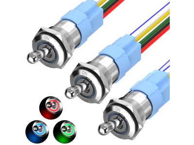
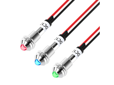
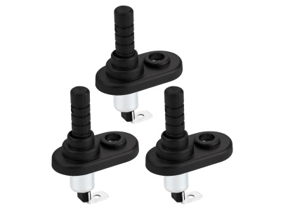
An auxiliary light setup needs separate decisions for control, load switching and circuit protection. The switch selects operation, a relay or suitable controller switches the lighting load, and a correctly specified fuse protects the circuit wiring. A relay may already be included in a lighting harness or control system, so the first step is identifying what is present.
The correct arrangement depends on the light, harness, power source and installation. A light-bar label, relay rating or spare panel position does not establish that the complete circuit is suitable.
1. Give Each Component a Separate Job
Start with the function of each part before choosing a product.
| Component | Main job | Check before selection |
|---|---|---|
| Switch | Provides manual control | Action, terminal diagram, illumination connections and mounting fit |
| Relay or controller | Switches the lighting load | Control requirements, load suitability and connection diagram |
| Fuse and holder | Provides overcurrent protection for the wiring | Fuse type, circuit requirements and holder suitability |
| Wiring and connectors | Carry supply and return current | Cable route, length, installation conditions and connection quality |
A relay does not replace a fuse. A fuse does not replace a switch. A larger contact rating does not correct an unsuitable wire, connector or protection arrangement.
2. Check the Existing Harness Before Adding Parts
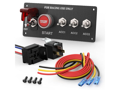
A supplied lighting harness may already contain a relay, inline fuse holder, switch and connectors. Identify those parts and read the harness instructions before adding another relay or changing the control.
Check whether the kit supports the intended number of lamps, the vehicle supply and the planned mounting locations. A plug that fits physically does not establish electrical compatibility.
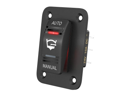
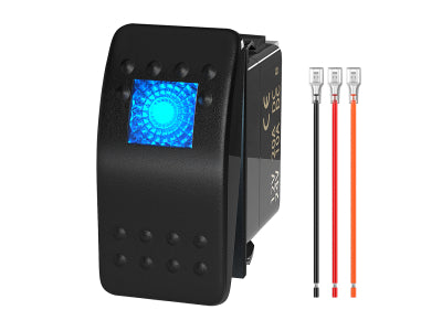
Replacing a harness switch with an illuminated rocker also requires a terminal check. Extra terminals may serve indicator or backlight functions rather than another lighting output. Preserve the documented control arrangement instead of matching wires by color alone.
An existing harness that meets the project requirements may only need an appropriate control location. Separate components make more sense when the supplied arrangement is incomplete, unsuitable or being redesigned.
3. Decide Where the Lighting Current Will Be Switched
In a conventional relay-controlled arrangement, the manual switch operates the relay coil while the relay contacts switch the lamp supply. This separates the dashboard control from the lighting load.
Use the lighting or harness instructions to determine whether an external relay is required. Some systems already contain relays or electronic switching, and another relay is not automatically an improvement.
Direct switching is an option only when the switch and complete circuit are documented as suitable for the actual load. An LED lamp can have startup behavior that differs from its steady operating current. The word LED alone does not establish that a small switch is adequate.
For a separate relay, confirm coil voltage, contact arrangement, load suitability and socket wiring. A relay containing a suppression diode must follow its marked coil polarity. The existing guide to relay operation and wiring explains the mechanism in more detail; the selected part's diagram remains the connection reference.
4. Specify Protection for the Actual Circuit
Select protection around the wiring and equipment requirements, rather than copying the largest number printed on the switch or relay. Fuse type, voltage rating and interrupting capability must suit the circuit; cable sizing also depends on route length, installation conditions and acceptable voltage drop.
Locate protection so the supply wiring is protected according to the equipment and vehicle instructions. A fuse positioned only beside the lamp can leave the upstream supply run unprotected. A branch using smaller wiring may need separate protection even when the main feed is already fused.
Included fuses are supplied components, not proof that every value suits every lamp. Repeated fuse failure needs diagnosis; increasing the fuse value without correcting the cause can compromise protection.
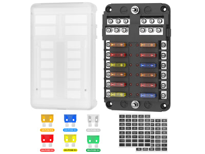
For several accessories, the 12V fuse-box buying guide covers distribution choices beyond a single inline holder.
5. Choose the Control Layout After the Circuit Plan
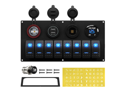
An individual ON/OFF rocker suits a dedicated lighting control. A grouped panel can organize several controls, but a row of switches does not necessarily include relays or independently protected outputs.
Separate a basic rocker panel from a control system supplied with a relay or electronic power module. Verify what each output does, its permitted load and the protection arrangement before connecting lamps.
Compare the Rocker Switch collection once the required action and terminal arrangement are known. The guide to switch panels versus separate rockers covers the mounting-layout decision.
6. Check the Installation Before Applying Power
Allow access to fuses, relay sockets and connections. Route cables away from heat, sharp edges and moving parts, and protect panel passages with suitable hardware. Support the wiring so connectors do not carry cable strain.
A covered switch or enclosure does not establish protection for every rear connection or cable entry. Check environmental limits for the installed assembly, especially in exposed locations. Vehicle and vessel return-path arrangements must follow the specific installation documentation.
Before applying power:
- Confirm the intended control action and any ignition-dependent behavior against the documented design.
- Check terminals, relay polarity where applicable, insulated connections and the complete return path.
- Confirm fuse selection and that every relevant supply or branch conductor has appropriate protection.
- Check cable routing, mounting security and service access.
Isolate the supply according to the equipment procedure before wiring work. Stop if existing parts show heat damage or the trigger connection is undocumented. An illuminated switch indicates only its own indicator state; it does not prove that the lamps receive the correct supply.
7. Related DAIER Products
Choose only the components missing from the documented arrangement. The following products are separate options, rather than a matched lighting kit.
- Dedicated manual control: DR-A11L25A-LJ34 LED light-bar rocker switch provides ON/OFF SPST control with dual illumination. Confirm the terminal diagram before replacing a harness switch.
- Separate load switching: JD1914-W12V relay with socket is a 12V-coil SPDT option. Check contact suitability, socket connections and marked coil polarity.
- Inline protection component: F117-C ATO/ATC fuse holder provides a covered inline holder format. Select the fuse variant from the circuit requirements.
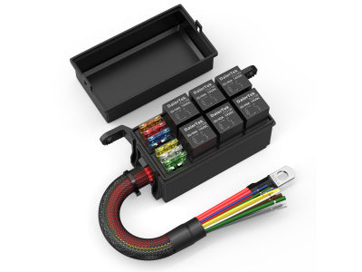
- Conditional system upgrade: RB-R6F6-W1 pre-wired fuse and relay box can organize multiple circuits. Verify the supplied layout, feed protection and branch assignments before use.


