


What to put on a 6-gang switch panel depends on which accessories need manual control, how often those controls are used, and whether any function needs a different switching arrangement. Start with the actual accessories, place suitable manual controls by priority, and leave a position open only when a future addition is likely. Six available positions do not require six connected accessories.
This plan assumes that a grouped panel already suits the installation. The earlier guide to switch panels and separate rocker switches covers that layout decision.
Start With the Accessories, Then Classify Their Controls
List each accessory before assigning labels. Note its purpose, frequency of use, and required control action. Auxiliary lighting and a manually operated ventilation fan are possible candidates; the final list depends on the actual installation.
Sort the list into regular manual controls, occasional manual controls, functions needing another control action, and automatic or independently available functions. An empty switch is not a reason to add an unsuitable load.
Separate Manual Switches From Automatic and Special Controls
A switch position does not establish the correct action for every accessory. An automatic bilge-pump function, alarm, or required vessel light needs an equipment-specific arrangement. Such functions do not belong in a generic manual ON/OFF example.
A motor, horn, compressor, or other demanding load may call for a different control arrangement. A spare ON/OFF position alone does not make it suitable.
Assign the Six Positions by Priority
Group suitable manual accessories by frequency of use. Place frequent controls where they can be identified and reached easily. Assign occasional, noncritical functions next. Labels should describe the connected function, not a vague “auxiliary.”
Illustrative six-position RV plan (not a fixed layout):
- Cabin lights — a regularly used manual control.
- Awning light — an exterior light used when needed.
- Storage-compartment light — an occasional manual control.
- Exterior work light — another occasional manual control.
- Manually operated ventilation fan — only when that fan's control requirements fit the chosen system.
- Open position — reserved for an identified future accessory, with no load connected yet.
The example shows a priority order, not a wiring plan or a prescribed arrangement for every RV, vehicle, or boat.

Illustrative control priorities; final assignments depend on the specific build.
First: Regular Manual Controls; Next: Occasional Controls
For a vehicle with several auxiliary lights, the work light used at every stop may deserve a more prominent position than a light used only during maintenance. In an RV, regularly used cabin lighting may rank ahead of an occasional exterior light. These are priority examples, not fixed left-to-right layouts.
Keep related controls distinguishable in the dark. Position order should follow the mounting location, visibility, and normal sequence of use.
Then: Check Special Controls and Leave Realistic Spare Capacity
Before assigning the remaining positions, check whether a proposed function uses a maintained manual switch or needs another control action. The accessory and panel instructions settle that decision.
One empty position can support an identified future accessory. An undefined “just in case” circuit needs no label or connection. If the verified plan requires more than six manual positions, reconsider capacity. The PN-RSP8 eight-position system is a conditional route only when eight positions are needed.
Illustrative Plans for Marine, RV, and Off-Road Builds
In a boat, noncritical cabin or deck lighting and a manually operated ventilation fan may occupy some positions. Automatic pump operation and required navigation-light control need separate, equipment-specific review. In an RV, cabin and awning lights plus a fan may rank highly. In an off-road vehicle, work and auxiliary lights may take priority.
Accessory count, control action, and installation requirements determine the remaining positions.
Match the Finished Plan to a Six-Gang Control Format
Once the functions are settled, compare the 6-gang rocker switch panel options by control format and mounting space.

Top left: PN-R6S3; top right: PN-R6-101EN; bottom left: PN-L6S1-P21; bottom right: PN-RSP6.
Conventional Rocker Panels for Straightforward ON/OFF Layouts
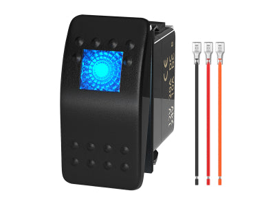
The PN-R6-101EN is a conventional six-position ON/OFF rocker panel for a straightforward group of manual controls. The PN-1816 adds dual-LED identification where locating and distinguishing controls matters.
Multifunction Panels and Surface-Mount Switch Boxes
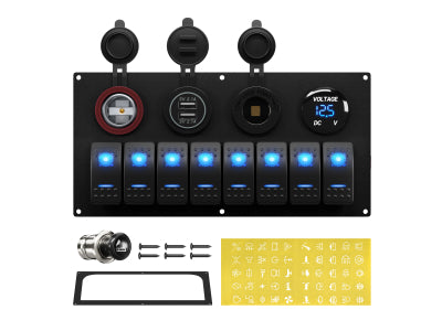
The PN-R6S3 is the primary multifunction option: a pre-wired six-position rocker panel with charging and voltage-display modules. It fits a plan that calls for those visible convenience functions alongside manual controls. The PN-L6S1-P21 provides a surface-mount switch box with charging and display modules where that enclosure style fits the installation.
A Separate Control-Box System When the Plan Requires One
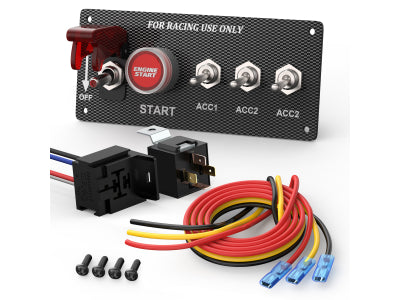
The PN-RSP6 uses a six-position control interface with a separate relay/control box. Consider that architecture when the completed accessory plan calls for a separate control system.
Across these formats, the accessory's control action, load compatibility, and branch protection still need to match the relevant product instructions. Integrated modules or a control box do not settle those decisions by themselves.

Control positions do not replace circuit protection or distribution planning.
Keep Control, Protection, and Distribution Separate
A six-position panel organizes control. Circuit protection addresses faults in the relevant branches, while distribution organizes the power feed and return paths. These are related decisions, but a row of switches does not establish a complete protected circuit for each accessory.
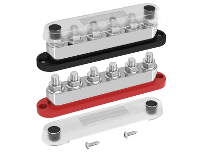
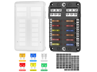
For a protection plan, see the guide to choosing a 12V fuse box. Where a distribution point is needed, the guide to choosing a 12V busbar explains that component's role. Return-path and protection choices remain specific to the equipment and installation.
FAQ: Final Planning Checks
Do all six switch positions need to be used?
No. An unused position is reasonable, especially when a defined future accessory may be added. Do not add a load simply to fill an empty switch.
Can a 6-gang panel switch a high-current accessory directly?
There is no universal answer. The accessory's load and required action, the panel architecture, and the relevant product instructions determine whether direct switching, a relay, or a dedicated system is appropriate.
Is a separate fuse box still needed?
The panel alone does not establish branch-circuit protection. The required protection and distribution arrangement depends on the selected products and the complete electrical design.
Related DAIER Products
- Multifunction six-position option — primary: PN-R6S3 six-gang multifunction rocker panel — for a six-position plan that also calls for charging and display modules.
- Straightforward manual controls: PN-R6-101EN six-gang rocker panel — for conventional manual ON/OFF controls.
- Clearer switch identification: PN-1816 dual-LED six-gang panel — when switch identification and illumination matter.
- Surface-mount convenience: PN-L6S1-P21 six-gang switch box — for a surface-mount format with charging and display modules.
- Separate control system: PN-RSP6 six-gang control-box system — when a separate relay/control-box architecture is called for.


